Lobe Compressor Diagram . There are single or twin lobes attached to the drive shaft driven by the prime mover. lobe blowers consist of two rotors spinning in opposite directions. operation of the familiar basic rotary lobe blower is illustrated in figure 1, where air flow is top to bottom from inlet to. When the compression chamber comes into contact with the outlet port, compressed air flows back into the housing from the pressure side. The blower sucks in air, and the lobes spin the air around before pushing the air out. the lobe type air compressor is very simpler type with no complicated moving parts.
from www.at-minerals.com
the lobe type air compressor is very simpler type with no complicated moving parts. operation of the familiar basic rotary lobe blower is illustrated in figure 1, where air flow is top to bottom from inlet to. There are single or twin lobes attached to the drive shaft driven by the prime mover. lobe blowers consist of two rotors spinning in opposite directions. The blower sucks in air, and the lobes spin the air around before pushing the air out. When the compression chamber comes into contact with the outlet port, compressed air flows back into the housing from the pressure side.
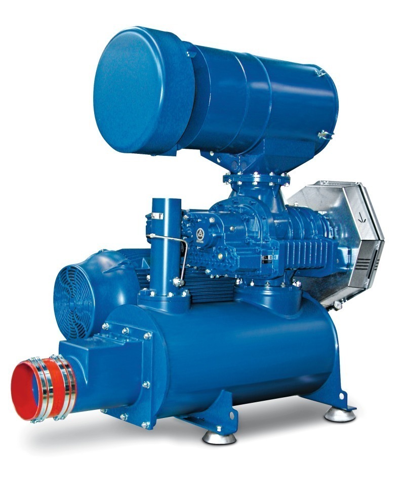
Extension of new rotary lobe compressor series Mineral Processing
Lobe Compressor Diagram There are single or twin lobes attached to the drive shaft driven by the prime mover. operation of the familiar basic rotary lobe blower is illustrated in figure 1, where air flow is top to bottom from inlet to. The blower sucks in air, and the lobes spin the air around before pushing the air out. When the compression chamber comes into contact with the outlet port, compressed air flows back into the housing from the pressure side. lobe blowers consist of two rotors spinning in opposite directions. the lobe type air compressor is very simpler type with no complicated moving parts. There are single or twin lobes attached to the drive shaft driven by the prime mover.
From www.youtube.com
Roots Blower Five Lobe YouTube Lobe Compressor Diagram When the compression chamber comes into contact with the outlet port, compressed air flows back into the housing from the pressure side. There are single or twin lobes attached to the drive shaft driven by the prime mover. the lobe type air compressor is very simpler type with no complicated moving parts. lobe blowers consist of two rotors. Lobe Compressor Diagram.
From www.youtube.com
Lobe type Compressor YouTube Lobe Compressor Diagram the lobe type air compressor is very simpler type with no complicated moving parts. There are single or twin lobes attached to the drive shaft driven by the prime mover. operation of the familiar basic rotary lobe blower is illustrated in figure 1, where air flow is top to bottom from inlet to. The blower sucks in air,. Lobe Compressor Diagram.
From engineeringlearn.com
7 Types of Air Compressor Definition, Uses & Working Principle Lobe Compressor Diagram operation of the familiar basic rotary lobe blower is illustrated in figure 1, where air flow is top to bottom from inlet to. The blower sucks in air, and the lobes spin the air around before pushing the air out. the lobe type air compressor is very simpler type with no complicated moving parts. When the compression chamber. Lobe Compressor Diagram.
From amechieneer.com
Screw Compressor Working Principle The Mechanical Engineer Lobe Compressor Diagram operation of the familiar basic rotary lobe blower is illustrated in figure 1, where air flow is top to bottom from inlet to. The blower sucks in air, and the lobes spin the air around before pushing the air out. the lobe type air compressor is very simpler type with no complicated moving parts. There are single or. Lobe Compressor Diagram.
From www.youtube.com
NASH Twin Lobe Liquid Ring Compressor How It Works YouTube Lobe Compressor Diagram operation of the familiar basic rotary lobe blower is illustrated in figure 1, where air flow is top to bottom from inlet to. When the compression chamber comes into contact with the outlet port, compressed air flows back into the housing from the pressure side. There are single or twin lobes attached to the drive shaft driven by the. Lobe Compressor Diagram.
From www.at-minerals.com
Extension of new rotary lobe compressor series Mineral Processing Lobe Compressor Diagram When the compression chamber comes into contact with the outlet port, compressed air flows back into the housing from the pressure side. the lobe type air compressor is very simpler type with no complicated moving parts. The blower sucks in air, and the lobes spin the air around before pushing the air out. lobe blowers consist of two. Lobe Compressor Diagram.
From www.evomart.co.uk
Vol 7 Fundamentals Part 7 Compressors (Continued) Evomart Lobe Compressor Diagram lobe blowers consist of two rotors spinning in opposite directions. When the compression chamber comes into contact with the outlet port, compressed air flows back into the housing from the pressure side. The blower sucks in air, and the lobes spin the air around before pushing the air out. operation of the familiar basic rotary lobe blower is. Lobe Compressor Diagram.
From www.youtube.com
lobe compressor YouTube Lobe Compressor Diagram operation of the familiar basic rotary lobe blower is illustrated in figure 1, where air flow is top to bottom from inlet to. There are single or twin lobes attached to the drive shaft driven by the prime mover. The blower sucks in air, and the lobes spin the air around before pushing the air out. When the compression. Lobe Compressor Diagram.
From www.brighthubengineering.com
Types of Air Compressors Reciprocating, Rotary, Screw, Vane, Lobe Lobe Compressor Diagram The blower sucks in air, and the lobes spin the air around before pushing the air out. the lobe type air compressor is very simpler type with no complicated moving parts. When the compression chamber comes into contact with the outlet port, compressed air flows back into the housing from the pressure side. operation of the familiar basic. Lobe Compressor Diagram.
From chempedia.info
Compressors HelicalLobe Big Chemical Encyclopedia Lobe Compressor Diagram When the compression chamber comes into contact with the outlet port, compressed air flows back into the housing from the pressure side. operation of the familiar basic rotary lobe blower is illustrated in figure 1, where air flow is top to bottom from inlet to. the lobe type air compressor is very simpler type with no complicated moving. Lobe Compressor Diagram.
From www.linquip.com
4 Types of Air Compressors & Application) Linquip Lobe Compressor Diagram The blower sucks in air, and the lobes spin the air around before pushing the air out. lobe blowers consist of two rotors spinning in opposite directions. operation of the familiar basic rotary lobe blower is illustrated in figure 1, where air flow is top to bottom from inlet to. the lobe type air compressor is very. Lobe Compressor Diagram.
From www.bigrentz.com
How Air Compressors Work An Animated Guide BigRentz Lobe Compressor Diagram When the compression chamber comes into contact with the outlet port, compressed air flows back into the housing from the pressure side. The blower sucks in air, and the lobes spin the air around before pushing the air out. There are single or twin lobes attached to the drive shaft driven by the prime mover. the lobe type air. Lobe Compressor Diagram.
From www.sunrise-metal.com
Oilfree Compressor Parts Construction of Different Oilfree Compressors Lobe Compressor Diagram operation of the familiar basic rotary lobe blower is illustrated in figure 1, where air flow is top to bottom from inlet to. The blower sucks in air, and the lobes spin the air around before pushing the air out. lobe blowers consist of two rotors spinning in opposite directions. There are single or twin lobes attached to. Lobe Compressor Diagram.
From instrumentationtools.com
Rotary Compressors Inst Tools Lobe Compressor Diagram There are single or twin lobes attached to the drive shaft driven by the prime mover. lobe blowers consist of two rotors spinning in opposite directions. operation of the familiar basic rotary lobe blower is illustrated in figure 1, where air flow is top to bottom from inlet to. When the compression chamber comes into contact with the. Lobe Compressor Diagram.
From dokumen.tips
(PDF) Chapter 13 Straight Lobe Compressor DOKUMEN.TIPS Lobe Compressor Diagram operation of the familiar basic rotary lobe blower is illustrated in figure 1, where air flow is top to bottom from inlet to. The blower sucks in air, and the lobes spin the air around before pushing the air out. There are single or twin lobes attached to the drive shaft driven by the prime mover. lobe blowers. Lobe Compressor Diagram.
From www.youtube.com
Lobe Compressor Simulation with CONVERGE YouTube Lobe Compressor Diagram operation of the familiar basic rotary lobe blower is illustrated in figure 1, where air flow is top to bottom from inlet to. When the compression chamber comes into contact with the outlet port, compressed air flows back into the housing from the pressure side. the lobe type air compressor is very simpler type with no complicated moving. Lobe Compressor Diagram.
From www.sunrise-metal.com
Oilfree Compressor Parts Construction of Different Oilfree Compressors Lobe Compressor Diagram The blower sucks in air, and the lobes spin the air around before pushing the air out. lobe blowers consist of two rotors spinning in opposite directions. When the compression chamber comes into contact with the outlet port, compressed air flows back into the housing from the pressure side. There are single or twin lobes attached to the drive. Lobe Compressor Diagram.
From www.pumpandvalve.com
Rotary Lobe Pumps New Zealand Pump and Valve Specialties Lobe Compressor Diagram lobe blowers consist of two rotors spinning in opposite directions. the lobe type air compressor is very simpler type with no complicated moving parts. The blower sucks in air, and the lobes spin the air around before pushing the air out. When the compression chamber comes into contact with the outlet port, compressed air flows back into the. Lobe Compressor Diagram.